Detail Drawing.
A detail drawing is a large-scale technical drawing that isolates a specific part of a building to show its materials, dimensions, and assembly with precision. It provides the close-up information that smaller-scale plans and elevations cannot convey. Detail drawings are essential for accurate construction and clear communication between designers and builders.
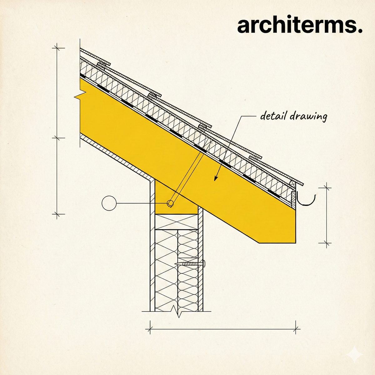
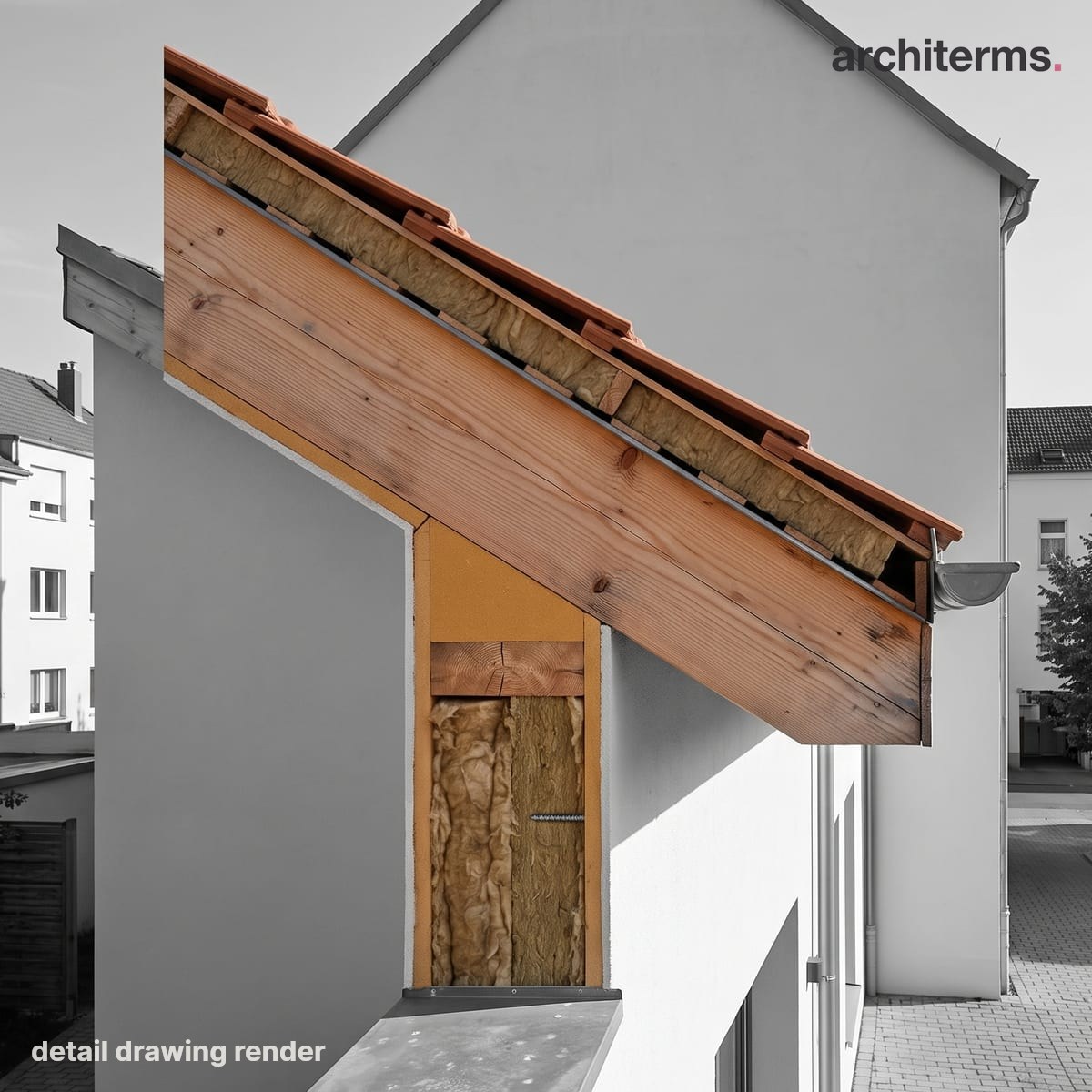
A detail drawing zooms in on one junction, here a window jamb, at a scale large enough to show each material, its thickness, and how the parts meet. It carries the dimensions and notes that a plan or elevation is too small to hold.
Visualized with Reviz.Design — AI rendering for architects and interior designers
Definition
A detail drawing is a drawing produced at an enlarged scale—commonly 1:10, 1:5, 1:2, or full size (1:1)—that focuses on a discrete portion of a building to communicate exactly how its components fit together. Where a Floor Plan or Elevation describes the overall arrangement of a structure, a detail drawing zooms into a junction, edge, or connection and specifies the materials, dimensions, fixings, tolerances, and construction sequence required to build it correctly. Typical subjects include a window jamb, a parapet coping, a roof eaves, a stair nosing, or the meeting of a wall and floor. Because these drawings carry information that is too small to read at architectural scale, they form a critical layer of the construction document set and are usually cross-referenced from the broader plans and sections by a key symbol or callout.
Detail Drawing History
The practice of drawing building parts at enlarged scale grew alongside the development of measured architectural drawing itself. Renaissance architects and master masons recorded mouldings, capitals, and profiles at large scale so that carvers and stonecutters could reproduce them faithfully on site. Treatises such as those by Vitruvius, later revived and illustrated, and the printed pattern books of the sixteenth and seventeenth centuries circulated precise profiles of a Cornice, an Architrave, or a Capital so that builders far from the designer could replicate classical forms. As construction grew more complex during the Industrial Revolution, the separation between the person who designed a building and the many trades who built it widened, and the detail drawing became the formal instrument that bridged that gap. The rise of standardized engineering drawing in the nineteenth century, with its conventions of orthographic projection, dimensioning, and sectioning, gave the architectural detail its modern form. By the time iron, steel, and large sheets of glass entered everyday building, detailing junctions accurately was no longer optional but central to keeping a building weathertight and structurally sound.
Detail Drawing in Architecture
In contemporary practice, detail drawings are prepared during the technical design and construction documentation stages and are issued to contractors, fabricators, and building-control authorities. A modern set might include a wall Section detail showing the layered build-up of a Cavity Wall, the position of insulation, and the location of Flashing at an opening; a roof detail showing how a Rafter meets a wall plate; or a balustrade detail dimensioning each baluster and handrail. Critical performance issues—rainwater management at a Parapet, thermal bridging at a slab edge, movement joints, and the routing of damp-proof courses—are resolved at this scale rather than in general arrangement drawings. Many offices maintain libraries of standard details that are adapted for each project, while bespoke conditions are drawn from scratch. Detail drawings are increasingly produced within Building Information Modelling environments, where a three-dimensional model can generate consistent two-dimensional details automatically, though the designer still curates and annotates each one. Because a poorly resolved junction can cause water ingress, condensation, or failure, the quality of a building's detailing is often regarded as a direct measure of an architect's technical skill, in much the same way that careful material connections distinguish good engineering practice in any built structure.
Common confusion
Detail drawings are frequently confused with sections, and the two are closely related but not identical. A Section is a cut taken through an entire building or a substantial part of it to reveal vertical relationships at architectural scale, whereas a detail drawing is a magnified study of one small region—often itself drawn as a section, but enlarged and heavily annotated. In other words, a detail may be a section, but a section is rarely a detail. People also confuse detail drawings with shop drawings: a shop drawing is produced by a fabricator or subcontractor to show how they intend to manufacture and install a component, and it must comply with the architect's detail drawing rather than replace it. Detail drawings are also distinct from general assembly or general arrangement drawings, which show the whole at a smaller scale without the close-up resolution. Finally, the term should not be mistaken for an ornamental "detail" in the decorative sense—such as a carved Frieze or moulding profile—although a detail drawing may indeed be used to document exactly such ornament. The defining characteristic is always the enlarged scale and the precise, buildable information it carries, not the subject matter itself.
Frequently Asked Questions
What scale is a detail drawing usually drawn at?
Detail drawings are typically drawn at enlarged scales such as 1:10, 1:5, 1:2, or full size (1:1). The larger scale allows materials, dimensions, and connections to be shown clearly. The exact scale chosen depends on how much information the junction needs to convey.
What is the difference between a detail drawing and a section?
A section cuts through an entire building or a large portion of it at architectural scale to show vertical relationships, while a detail drawing magnifies one small region and annotates it heavily. A detail is often itself a small section, but enlarged and far more specific. In short, a detail may be a section, but a section is rarely a detail.
Why are detail drawings important in construction?
Detail drawings communicate exactly how building components fit together, including materials, fixings, and tolerances that smaller-scale drawings cannot show. They help prevent problems such as water ingress, thermal bridging, and structural failure at junctions. They are also the reference against which contractors and fabricators check their own shop drawings.
What are common examples of detail drawings?
Common examples include window jambs, roof eaves, parapet copings, stair nosings, balustrade connections, and wall-to-floor junctions. Each isolates a specific construction condition and resolves it at enlarged scale. Many offices keep libraries of standard details that are adapted for individual projects.